
I recently have been lucky enough to put my hands on the VW Haldex Service Training – Self Study Program (no. 89C303). And since I get a lot of questions about it, here’s the integral document. (Haldex section) BTW, it’s as good for the Audi TT Haldex.
Enjoy!
Andre
PS Also see: HPA’s Haldex Performance Controller and Haldex Controller Update: Blue – Orange – Silver Controllers.
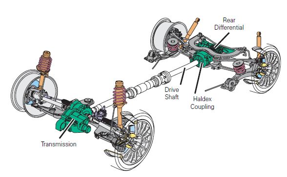
Haldex Coupling
The development of the Haldex coupling is a giant step forward in modern all-wheel-drive technology. This coupling is controllable, based on the inputs the Haldex control module receives from the vehicle. Slip is no longer the only decisive factor in the distribution of drive forces — the car’s dynamic state is also a factor. The Haldex control module monitors the ABS wheel speed sensors and the engine control module (accelerator pedal signal) via the CAN-bus. This data provides the engine control module with all the information it needs on road speed, cornering, coasting or traction mode, and can respond optimally to any driving situation.
Characteristics of the Haldex coupling:
• Permanent all-wheel drive with electronically controlled multi-plate clutch
• Front drive characteristic
• Quick response
• No strain on clutch when parking and maneuvering vehicle
• Compatible with different tires (e.g., emergency wheel)
• No restrictions on towing with the rear axle on the ground
• Fully integrates with systems such as the Anti-Lock Brake System (ABS), Electronic Differential Lock (EDL), Anti-Slip Regulation (ASR), Electronic Brake Distribution system (EBD), and Electronic Stabilization Program (ESP)

Haldex-Coupling
The Haldex coupling is mounted on the rear axle differential and is driven by the drive shaft. Engine torque is transmitted to the drive shaft through the gearbox, the front axle differential, and the front axle drive The drive shaft is connected to the input shaft of the Haldex coupling. In the Haldex coupling, the input shaft is separated from the output shaft to the rear axle differential. Torque can only be transmitted to the rear axle differential when the Haldex coupling clutch plates are engaged.


Haldex System
The parts include:
• Input shaft
• Inner and outer clutch plates
• Lifting plate
• Roller bearing with annular piston
• Output shaft
The electronics are:
• Pump for Haldex coupling
• Regulating valve positioning motor
• Temperature sensor
• Haldex control module
The hydraulics are:
• Pressure valves
• Accumulator
• Oil filter
• Annular piston
• Regulating valve

Multi-Plate Clutch The clutch input shaft, indicated in blue in the illustration below, is connected to the prop shaft. The roller bearings for the lifting piston and the working piston, as well as the outer clutch plates, are engaged when the input shaft rotates.
The lifting and working pistons are annular pistons. The output shaft, indicated in red in the figure, forms a unit from the lifting plate through to the drive pinion head. The inner clutch plates are also connected to the output shaft via longitudinal toothing.

Function When a speed difference is present between the input and output shafts, the input shaft, together with the roller bearing of the lifting piston, rotates around the still stationary lifting plate of the output shaft. The roller bearing of the lifting piston tracks along the undulating surface of the lifting plate. The roller transfers these upward and downward movements to the lifting piston, causing it to perform a lift movement, building up oil pressure.
Oil pressure is diverted via an oil duct to the working piston, forcing the working piston to move to the left against the roller bearings and the pressure plate of the clutch plate set. The clutch plate set is compressed. The input shaft and the output shaft of the clutch are now interconnected, connecting both the front and rear axles and making allwheel drive possible.

When a difference in speeds occurs between the front and rear axles, the outer clutch plate housing, together with the roller bearings, rotates around the output shaft in such a way that the roller bearings of the lifting piston roll on the lifting plate.
Due to the shape of the lifting plate, the roller bearings of the lifting piston follow an undulating path and transfer the lifting movement to the lifting pistons in the housing.
The output shaft, with its splines for the inner clutch plate, combines with the lifting plate and the drive pinion head to form a unit.
! The roller bearings are shown here for your information only.
! For reasons of clarity, we have shown the lifting plate with two cams. In reality, there are three cams on the lifting plate. The function remains unchanged.

The outer clutch plate housing, together with the splines for the outer clutch plate and roller bearings, combine with the input shaft to form a unit.
The movement of the lifting piston produces an oil pressure which acts on the working piston via the oil duct, pushing the piston to the left.
Pressure is transferred via a pressure plate to the clutch plate set and the roller bearings of the working piston. The clutch closes and thus interconnects the front and rear axles.
! The roller bearings are located in the outer clutch plate housing, as shown here. These roller bearings are shown here for your information only.

Diagram of the Oil Pressure System
The pressure limiting valve determines the maximum pressure on the clutch plates.
You have already seen how oil pressure is built up at the lifting piston as a result of a difference in speeds between the input shaft (blue) and the output shaft with lifting plate (red).
This oil pressure is regulated by valves. The clutch plate can thus allow a certain amount of slip when open and nearly closed.
! For reasons of clarity, we explained function on the previous pages using a lifting piston by way of an example. In reality, there are two lifting pistons in the clutch housing — these pistons are actuated by roller bearing pairs. Therefore, two suction valves and two pressure valves are also required.

Diagram of the Oil Pressure System


Motronic Engine Control Module (ECM) J220
This control module is mounted in different areas on the various vehicles, but is normally accommodated in the plenum chamber. The operating mode of J220 is torque-oriented.
Signal Utilization for the All-Wheel Drive Electronics
J220 provides the following signals to the All-Wheel Drive (Haldex) Control Module J492 along the CAN-bus:
• Engine speed signal
• Accelerator pedal position
• Engine torque
Effects of signal failure:
• The Haldex coupling will not operate
 J220")
Engine Speed (RPM) Sensor G28
G28 is an inductive sensor and is installed near the oil filter on the left-hand side of the engine.
Signal Utilization
This sensor records in the exact angular position of the crankshaft to determine the ignition and injection point, as well as engine speed.
Engine Speed
As soon as the engine turns, the sensor wheel moves past G28 and generates an alternating current (AC) voltage. The frequency and amplitude of this voltage changes with engine speed.
Motronic ECM J220 calculates engine speed from the frequency of the AC voltage.
Ignition Point
To recognize crankshaft position, the sensor wheel has a larger gap trigger tooth which serves as a reference mark.
ffects of Signal
Failure If the engine speed signal supplied by G28 fails, the engine will not start or run.
If no engine speed signal is received, the Haldex control module J492 will not energize the pump, leaving rear axle drive capability disabled. This also allows the vehicle to be towed with the rear wheels on the ground because no power is transmitted back through the wheels to the transmission.
 Sensor G28")
Engine Speed (RPM) Sensor G28
Throttle Position Sensor G79 and Sender 2 for Accelerator Pedal Position G185
Two independent potentiometers, G79 and G185, work together to receive and send accelerator pedal position analog signals to Motronic ECM J220.
Haldex control module J492 uses these signals in combination with other signals to determine when and how much power should be applied to the rear axle. G79 and G185 represents the driver intention, and is not necessarily how J220 is allowing the engine to operate.
Effects of Signal Failure
J220 monitors G79 and G185 for proper functioning and plausibility. If one of these two fails, the other sensor/sender acts as a back-up. The Electronic Power Control (EPC) Warning Lamp K132 on the instrument cluster will illuminate and the vehicle will enter emergency running mode.
If this signal is not available to the Haldex control module J492, all-wheel drive will not be available.

ABS Control Module J104
This control module is combined with the hydraulic unit, which is mounted in the engine compartment on the left-hand side. When the ignition is turned on, the control modules carry out a self-test.
This control module consists of two processor systems, which ensures a high level of fail-safety. In addition to monitoring individual components, the two processor systems monitor each other.
Signal Utilization for All-Wheel-Drive Electronics
The following signals are supplied to the Haldex control module J492 along the CANbus:
• ABS Wheel Speed Sensors G44 and G47
• Brake Light Switch F9
• Parking Brake Light Switch F9
• Longitudinal Acceleration Sensor G251
Effects of Signal Failure
In the unlikely event of total failure of the control module, the Haldex unit will not function properly.

Right Rear and Left Front ABS Wheel Speed Sensors G44 and G47
These sensors detect changes in wheel speed, sending this information to ABS Control Module J104 in the form of wheel speed information. This information is then sent to Haldex control module J492 via CAN-bus.
Each wheel speed sensor is mounted in the vicinity of the axle flange. A toothed wheel is positioned on the axle flange in such a way that it moves past the top end of the wheel speed sensor when the wheel rotates.
Magnetic lines of force between the tooth and tooth gap of the toothed wheel are distorted. This induces a sine-wave AC voltage in the coil of the engine speed sensor.
The frequency and amplitude in the coil is dependent on wheel speed. J104 calculates the momentary speed of individual wheels from the frequency. Effects of signal failure:
• No ABS control
• No all-wheel drive control

Right Rear and Left Front ABS Wheel Speed Sensors G44 and G47
ESP Sensor Unit G419
ESP Sensor Unit G419 combines the functionality of two sensors, Sensor for Transverse Acceleration G200 and Sensor for Rotation Rate G202. This combined sensor is located on a bracket in the steering column area, under the instrument cluster. G419 is able to measure both transverse acceleration and rotational rate or yaw.
Effects of Signal Failure
Without the measurement of transverse acceleration or rotational rate, it is not possible for the ABS Control Module J104 to determine if ESP intervention is necessary. As a result, ESP and ASR will not operate, and the ESP light will illuminate in the instrument cluster.
Electrical Circuit
G419 is connected to J104 via four wires.

ESP Sensor Unit G419
Brake Light Switch F
This switch is located at the upper end of the brake pedal and is secured to the pedal support.
Signal Utilization
This brake light switch sends the “brake activated” signal to ABS Control Module J104, which informs Haldex control module J492 along the CAN-bus.
When the brake is applied, J492 immediately opens the pressure regulator via the positioning motor, opening the Haldex coupling clutch.
Effect of Signal Failure
The information provided by the CAN-bus is used as an alternative.

Brake Light Switch F
Parking Brake Warning Light F9
This switch is located under the parking brake lever.
Signal Utilization
F9 sends the “parking brake engaged” signal simultaneously to ABS Control Module J104 and the Haldex control module J492.
If the signal generated by F9 is picked up, the Haldex coupling clutch is opened.
Effects of Signal Failure
If the switch remains closed, then no allwheel drive control is available and restrictions are placed on ABS control.

Parking Brake Warning Light F9
Hydraulic Temperature Sensor G271
This sensor is installed near the regulating valve in the Haldex control module J492 housing and is immersed in hydraulic fluid.
Signal Utilization
G271 senses current hydraulic oil temperature, sending this information to J492. This information is used for constant adaptation to the changing hydraulic fluid viscosity.
If the hydraulic fluid temperature exceeds 100°C, the clutch is released. If the temperature of the hydraulic fluid drops below 100°C, the clutch is again pressurized.
Effects of Signal Failure
All-wheel drive is shut off if no signal is received from G271.

Hydraulic Temperature Sensor G271

All-Wheel Drive (Haldex) Control Module J492
This control module is mounted directly on the housing of the Haldex coupling and combines with the positioning motor and the regulating valve to form a unit.
Design and Function
J492 is connected to the engine and ABS control module J104 via the CAN-bus. From the signals that are generated by Motronic ECM J220 sensors, J492 decides what oil pressure to apply to the plates of the Haldex coupling clutch.
The oil pressure acting on the plates of the Haldex coupling clutch determine what torque is to be transmitted to the rear axle.
Effects of Signal Failure
If J492 is not operating correctly, no all-wheel drive is possible.
! Use address word 22 to access All-Wheel Drive (Haldex) Control Module J492.

Oil Pressure Actuator V184
This positioning motor is integrated in the Haldex control module J492 housing.
Design and Function
V184 is supplied with voltage by J492 and functions as a stepping motor.
At the command of J492, the positioning motor changes the level of the regulating pin in the pressure regulator via a small pinion gear.
The level of the regulating pin changes the cross section of a return bore in the pressure regulator. This controls the pressure acting on the working piston, and in turn, on the clutch plates.

Oil Pressure Actuator V184
Haldex Clutch Pump V181
The pump for the Haldex coupling is attached to the Haldex coupling housing.
Design
After the engine has been started, the pump for the Haldex coupling is supplied with voltage by Haldex control module J492 as soon as engine speed exceeds 400 rpm.
Function
The pump for the Haldex clutch conveys oil to the lifting piston and brings the lifting piston into contact with the lifting plate via roller bearings.
At the same time, oil reaches the working piston. This eliminates any play from the clutch plate set and ensures quick clutch response.
Effects of Signal Failure
If V181 is not operating correctly, no all-wheel drive is possible.
! The Haldex clutch pump is directly supplied with voltage by J492.


Self-Diagnosis
Haldex self-diagnosis electrically monitors:
• Signals generated by the sensors
• Activation of the positioning motors
• Haldex control module J492
If J492 detects a fault, it calculates a substitute value from other signals and makes an emergency running program available.
In the data transfer facility, the following functions can be read out under the address word 22 “4-wheel-drive electronics” via the VAS 5051 or VAS 5052:
02 Check DTC Memory
03 Output Diagnostic Test Mode (DTM)
05 Erase DTC Memory
06 End Output
08 Read Measuring Value Block


Pingback: HPA’s Haldex Performance Controller | Audi TT RS Project (3.2 V6 MK1 -8N- Turbo)
Pingback: Haldex Controller Update | Audi TT RS Project (3.2 V6 MK1 -8N- Turbo)
Pingback: haldex controller tt
Pingback: Sender Tuning Audi | Audi Photos Blog
Excellent that someone spends time on this, thanks ! I have a 1999 TT 225 hp 4wd, which sets a warning light in the dash and cuts off the rwd ( which is then stuck until the ignition has been turned off and then on again!) The traction control can not be activated in 1 st gear, 2 gear at 6500 RPM´s and up where there is torque transmitted, and in higher gears it kicks in when torque is applied. On a rainy day like today 4th gear at 60 MPH without too much throttle activates the system with water on the road ( it doesn’t reset automatically afterwards), 5th and 6th gear from 65 MPH and up when torque is in demand activates the fault. No fault readings in the diagnosis tool – no other flaws to report besides this. What´s your opinion on a probable cause ?
Hi there,
Thanks for the thumbs up!
As for your problem, it’s a tricky question. The traction control should create a fault reading. On big turbo systems like mine, we see this happening as the accelerometer gets confused by the amount of power it gets. Other possibilities, all related to each other are the ABS sensors or mass air flow.
The Haldex controller may be at fault, but I doubt it. Did you change your Haldex oil/filter recently? (I wouldn’t generate an in dash fault but who knows)
Let me know how this turns out.
Andre
Hello, please help me to detect a fault. Quickly lose oil through the hose “A” (identified on the website http://www.awdwiki.com/en/haldex/ “leaving the clutch and stops above the chassis, then I do not have rear-wheel drive. What is the cause?
It is a VW Sharan manufactured in 2006.
Thank you very much!
Thanks, I work on these at a VAG repair, APR tuner store have not had a problem child yet this information will be helpful, yes we have a stage III tt rs hitting the pavement soon with 600 hp, the owner dumped his V10 R8 to buy this car
Hi and thanks a lot for all these information.
I have a 2000 tt quattro and the initial problem was that the four wheel drive was not working. I took the car to the mechanic who removed the haldex and we discovered that the Haldex Clutch Pump V181 was full of oil. We managed to clean it and got it to work again. Now the four wheel drive works, however it appears that all wheels get the same power all the time. When the car is at first gear and the wheel is turned left or right when you accelerate you get the feeling that the back wheels are dragging. Also sometimes as i drive the car gets in safe mode (the car wont accelerate and the gas pedal doesn’t respond) and you need to switch off the car and start again which is very dangerous. Since my mechanic is a inexperienced in this system however is my cousin and need to stick with him i need to do all the work in discovering the error :). Please since you appear to know the system so good can you pleaseeee advice me.
It seems to me that you are experiencing more than one problem with your TT!
If the V181 was full of oil you are lucky your motor is still working. Most of the time, when the oil has penetrated in the electric side of the motor, the harm is done. The motor will eventually fail and stop working. The good thing on the other hand is as long it works, it means it is strong enough to prime the oil system. Therefore, you should plan the replacement or the rebuild of the pump to avoid erratic working.
When your cousin performed the repair, if he did not use specific formulated oil for the Haldex system, he may have created the locking problem you are experiencing. But it will have to be confirmed by further tests. At first he will have to confirm the oil level is good and the proper fluid is used. The last problem with the car that is falling on safe mode should not be linked with what is happening to the rear end. The car must be first be scanned using a VAG COM or similar to read the codes and see what it is pointing to. We hope it helps & keep us posted.
Andre
I was going to replace the haldex system with a used one but after my mechanic talked with a mechanic from audi he was adviced to change again the oils. The think is that we have replaced the oil of the haldex and i had checked online which one to use and ordered it so it should have been the right one. Can you advice on the part no of the oil to use. We have used G052175.
Regarding the safe mode after he further checked he told me that some rubber on the turbo needed replacement and maybe that was the cause. He scanned the car using a diagnostic and the indication was the speed sensor?!
Pingback: 50/50 haldex mod - Page 8
Hi Andre!
I have a 2002 Sharan 4motion, and the problem is when I taking slow corners with steering wheel in lock position, I hear loud grinding noise from the rear differential. I replaced the whole rear diff with the haldex but still the same. When I take out the fuse for the haldex, the noise is gone.
Thank you!
Hey Lukacs,
Please contact my friends at YHW: https://www.facebook.com/pages/Your-Haldex-Works/534748219887317
They will help you as they are the best Haldex people you can find.
Good luck!
Andre
Amazing write… very useful… tons of thanks
I have a mk 2 Audi TT . After getting it scanned the fault code was v181 Haldex clutch pump open circuit. Is this more than likely to be a electrical fault with the Haldex. On the dash I have the tpms signal constantly on.
I have a 2001 Audi TT Quattro with a big turbo. Almost everything is new or been replaced recently, but I have 190,000 miles on it. I havent replaced anything in the driveline except front cv axles. I change my haldex oil and filter every 8,000 miles or so. A while back I noticed in first gear or reverse my rear wheels where locked and it caused a skipping of the back wheel in a sharp turn. Recently the skipping rear wheel went away but under the same conditions (sharp turn in first or reverse) I hear a click click click noise coming from the haldex unit, I believe. Just last weekend I was on the highway and increased throttle slightly to pass somebody, and then let off the gas peddle and it created a jerking motion which turned on the esp light and put me in emergency running mode until I restarted the car. I would like to replace the clutch packs but cant find them anywhere to purchase. Im also thinking of getting a used haldex unit and just replacing it. What do you think my issue is?
It’s most probably your Haldex. I would replace the rear differential with a used one if you’re not interested in spending big dollars for a new one. Are you in the US? Found this on eBay UK: http://www.ebay.co.uk/itm/Audi-TT-8N-98-06-MK1-Quattro-3-2-V6-DSG-haldex-differential-diff-unit-complete-/131917190855.
Canada? Give these guys a ring: http://www.vagmotorsport.ca
Andre
I have an 01 TT 180hp 5speed Quattro. When I turn the key on,t he Haldex starts constantly clicking and such. VCDS reveals following:
Address 22: AWD Labels: 02D-900-554.lbl
Part No: 02D 900 554 B
Component: HALDEX LSC ECC 0006
VCID: 1F4DB4869D1311BE93-4B00
4 Faults Found:
65535 – Internal Control Module Memory Error
00-00 – –
01312 – Powertrain Data Bus
37-00 – Faulty
01316 – ABS Control Module
49-10 – No Communications – Intermittent
01314 – Engine Control Module
49-10 – No Communications – Intermittent
Address 03: ABS Brakes Labels: 8N0-907-379-MK20-E.lbl
Part No: 8N0 907 379 E
Component: ESP 20 CAN V005
Coding: 18446
Shop #: WSC 01236
VCID: 3E7369023AD978B6B8-4B00
1 Fault Found:
01324 – Control Module for All Wheel Drive (J492)
49-00 – No Communications
Yet ABS will function (tested in light gravel). ESP light (triangle) comes on once I drive about 10-15mph or faster and remains on until next key cycle.
Rick, I just saw your post. Did you get a fix yet?
No problem , yes it solved after rewrighting the softwear . I enjoy the wet Belgian asphalt again . Thanks for asking . Regards MALEK
Hi there
I live in BELGIUM probobly you notis that from my English , i have a Tiguan R-Line 130kw , it has gen5 haldex , first 2 years was perfect but than began with the front wheels spining when accerelating hard , i changed the kargo pump and oil but problem remains . back weels has a smal amount of power maybe %10 but it doesent vary i think its always the same .
Have you an idea ?
Sorry for the delay! Did you find the problem?
accelerating (sorry)
2002 Audi TT 225 ALMS Edition:
– Code Haldex Control Unit Failure.
– Changed the unit to a used one.
– Code Sporadic Mechanical Clutch Failure.
– Replaced ground wire that was rusted through.
– Rear wheels spinning on lift, however not under load.
– Replaced cargo pump and still no go under load.
– No Codes on VCDS/OBD11.
Any thoughts? Will be bringing to my mechanic to test all systems for any hidden codes, however at a loss.. I have been told the clutch packs are not common issue, so may try to change back to original haldex unit and check for any bad wires.
Hey Richard, sorry for the late response! Did you find a solution?